Multisim Circuit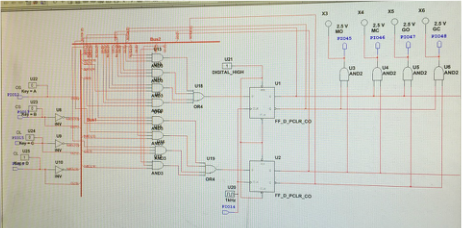
Transition Table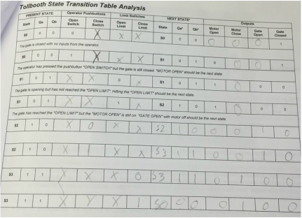
|
Working Prototype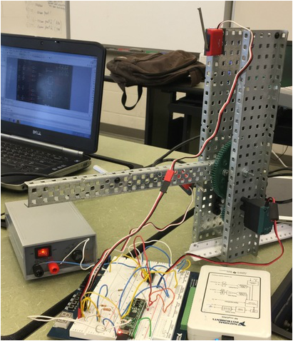
State Graph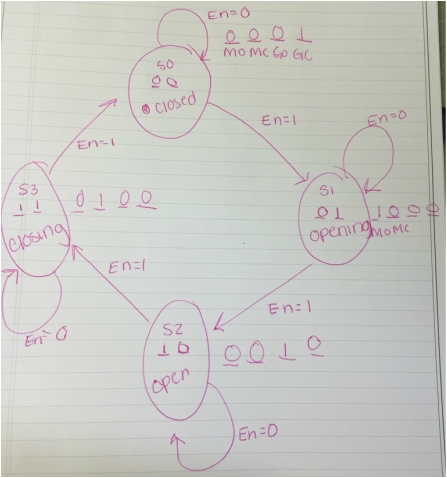
|
Conclusion
Dear Ms. Patrick,
My partner, Ian, and I had the task of designing a tollbooth which is controlled by a circuit we designed in Multisim. First we made our VEX structure. The VEX structure is composed of gears, motors, limit switches, and a lever. One problem we had when creating the VEX structure was the tollbooth arm not hitting the limit switch. We solved the problem by attaching a spacer to the tollbooth which hits the upper limit switch. Once we finished the VEX structure we had to start planning our circuit. We created a state graph which included 4 different states. The first state was a closed state where the closed indicator light emits. The second state is the opening state where the motor is running to open the gate after a button is pressed. The third state is the open state which causes the motor to stop running and is activated by the open limit switch. The fourth state is the closing state, activated by a switch, which causes the motor to run until the closed limit switch is hit causing the state to change to state 0, or closed. Next we made a transition table to create or design equation. The transition table was constructed from the State graph. The transition table allowed us to get the variables needed to K map each different scenario. After we K mapped it was time to complete our circuit in PLD mode of multisim. We used two busses, one for inputs and one for outputs and two D flip flops. We used LED's to see if our circuit worked, which it did the first try. The hardest part was bread boarding because we had to plug in the VEX machines such as the motor. Once we looked at the diagram in the packet it became much more clear. I started the bread boarding when Ian was not here by doing the basics and assigning pins to the chips, once Ian was here and I was not he was able to distinguish where each motor needed to be placed. We dowloaded our circuit onto the PLD and the tollbooth was successful. I enjoyed combining everything we learned this year in one project.
My partner, Ian, and I had the task of designing a tollbooth which is controlled by a circuit we designed in Multisim. First we made our VEX structure. The VEX structure is composed of gears, motors, limit switches, and a lever. One problem we had when creating the VEX structure was the tollbooth arm not hitting the limit switch. We solved the problem by attaching a spacer to the tollbooth which hits the upper limit switch. Once we finished the VEX structure we had to start planning our circuit. We created a state graph which included 4 different states. The first state was a closed state where the closed indicator light emits. The second state is the opening state where the motor is running to open the gate after a button is pressed. The third state is the open state which causes the motor to stop running and is activated by the open limit switch. The fourth state is the closing state, activated by a switch, which causes the motor to run until the closed limit switch is hit causing the state to change to state 0, or closed. Next we made a transition table to create or design equation. The transition table was constructed from the State graph. The transition table allowed us to get the variables needed to K map each different scenario. After we K mapped it was time to complete our circuit in PLD mode of multisim. We used two busses, one for inputs and one for outputs and two D flip flops. We used LED's to see if our circuit worked, which it did the first try. The hardest part was bread boarding because we had to plug in the VEX machines such as the motor. Once we looked at the diagram in the packet it became much more clear. I started the bread boarding when Ian was not here by doing the basics and assigning pins to the chips, once Ian was here and I was not he was able to distinguish where each motor needed to be placed. We dowloaded our circuit onto the PLD and the tollbooth was successful. I enjoyed combining everything we learned this year in one project.
