Logic ExpressionsP'VST+PV'S'T+PV'ST'+PV'ST+PVS'T'+PVS'T+PVST'+PVST
This unsimplified logic expression displays when the vote will pass P' means the president said no and P means the president said yes. Un-simplified Circuit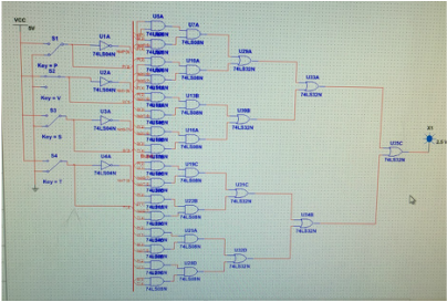
The un-simplified circuit is really confusing and uses 35 gates, making it expensive and inefficient to manufacture.
Simplified Circuit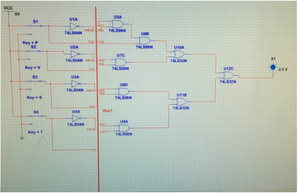
The simplified circuit is more efficient because it uses only 12 gates, which would also make it cheaper. The blue diode is emitted when the bill passes, and the switches are used to show who votes yes and who votes no.
|
Majority VoteIn a company a president, vice president, secretary, and treasurer are in charge of decision making for the company and in the event of a tie the president is the deciding factor. My task is to design a circuit that will determine the winner without the controversy of using a paper ballot system.
Truth Table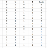
The truth table represents the different possibilities in the circuit. A zero on the truth table represents no and a one on the truth table represents yes. If the president (P) votes no the P column would have a 0. If the result has a 0 the bill did not pass but if the result has a 1 the bill passed. For example row one says 0 0 0 0 0, in context this means the president, vice president, secretary, and treasurer all voted no and the bill did not pass.
Boolean Algebra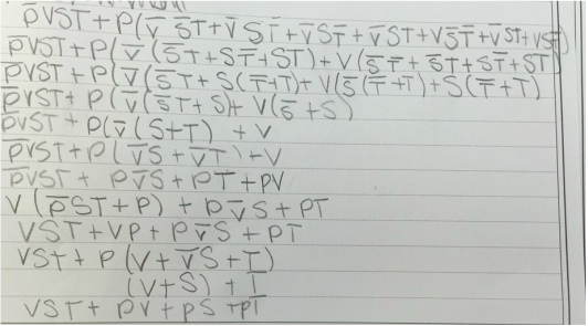
The simplified expression is VST+PV+PS+PT
Bill of Materials
Bread BoardngThe bread boarding process was very difficult at first because I didn't have the chart that shows in inputs of the gates and the outputs within the chips. The first time I completed the bread boarding I messed up by connecting the chips to the ground when they should have been connected to the power and connected to the power when it should have been connected to the ground. Without realizing this I tore apart my bread board and started over when it was just a silly mistake.
|
Conclusion
The majority vote project helped me put circuit building into a real word situation. I learned how to transfer my ideas on Multisim to the bread board. I learned that I should have tried to troubleshoot harder before I started completely over. The problem with my bread board was that I did not look at the chart that shows the inside of the IC chips. I should have connected space 14 to the power and space 7 to the ground, but I switched them. Also, I realized that the gates were inside the chips which I had trouble understanding before. I enjoyed the problem solving mind set while building the circuit, and how it made me think. I also enjoyed starting from a problem and using a truth table to get the logic expression then using Boolean algebra to get the simplified expression, then making my own circuit on Multisim, then transferring my circuit from Multisim into real life was educational. The hardest part of the circuit making process was the Boolean algebra. The hard part was not knowing whether I messed up on the first step or messed up on the last step. I had to ask for help with the Boolean algebra because I wanted to make sure I had it right before building my circuit on Multisim. I enjoy making circuits and I would even consider going into the electrical engineering field in the future.
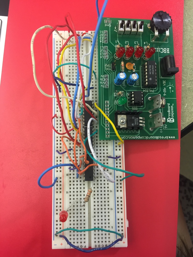
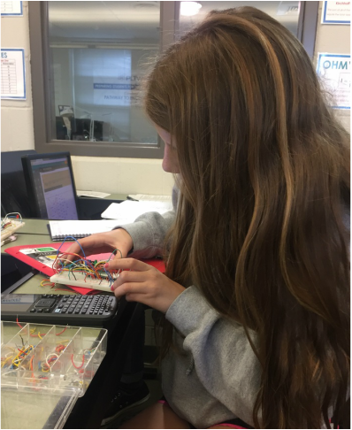
Bread Board (Top)Here you can see all the wires needed to bread board and the connections I made to make the LED light up..
|
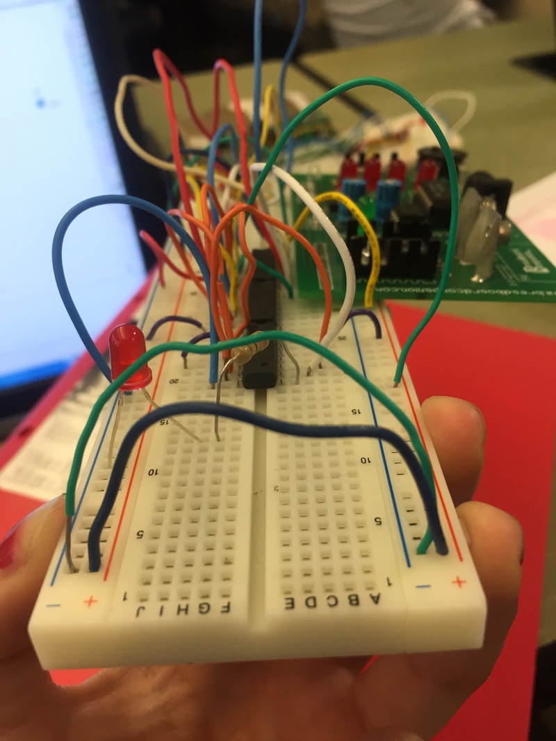
Bread Board (Side)Here you can see the wires bridging the board, connecting the positive side of the board to the other positive and the negative side to the other negative side.
|
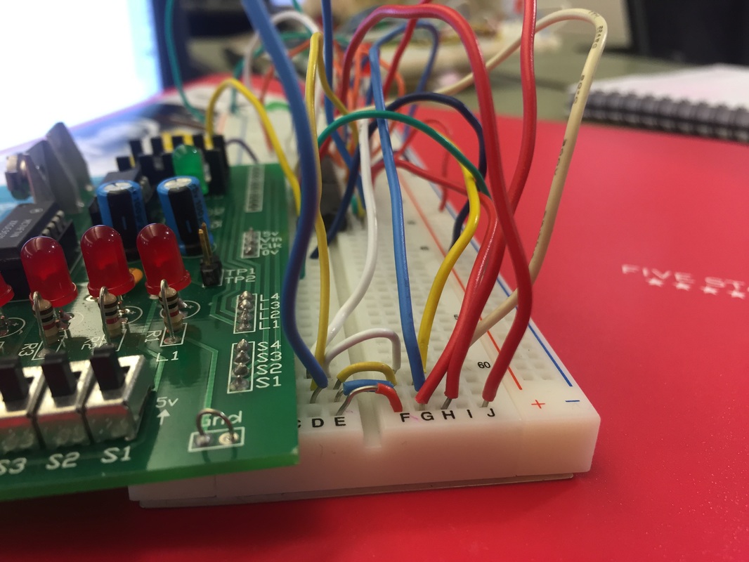
Bread Board CompanionThe bread boarding companion allows the bread board to be powered and also allows us to use switches. I used switch one on the bread board companion to be the President, switch 2, the vice president, 3 the secretary, and 4 the treasurer.
|
