Project OverviewThe criteria for the project was to create a display that counts from 0-59 like a timer would do. We had to create the circuit in multisim that uses small scale integration and medium scale integration that connect to 2 hex displays. The hex displays will display the tens digit (0-5) and the ones digit (0-9).
|
|
DMV Display vs 60 Second TimerThe DMV display and the 60 second timer were very similar projects. Both required small scale integration and medium scale integration as well as a reset switch. The difference was that the DMV display used a CNTR_4BIN_AS while the 60 second timer used a CNTR_4BIN_S counter for the ones place. The DMV display counted to 80 then paused while the 60 second timer counts to 59 then resets automatically. In both circuits you could reset the display at any time. Overall both projects had a lot of similarities and few differences.
Conclusion |
PLD Circuit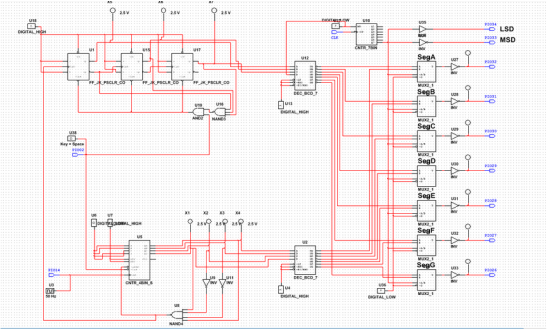
|
- Synchronous circuits are controlled by the same clock while asynchronous circuits are controlled by the previous flip flop and experience the ripple effect.
- The 74LS163 counter is different from the 74LS193 counter because the 74LS163 displays the number it detects, and is a synchronous counter while the 74LS193 chip displays the number before the number detected, and is an asynchronous counter.
- I created the circuit for the tens place by using the 74ls163 counter chip. I connected the input of the chip to display 0 by connecting A, B, C, and D to ground. After that, I had to program the output to detect a 9. I did so by connecting the wires to a four input NAND gate. I connected D and A to the gate and I connected B and C to inverts, then to the gate in order for the circuit to count to 9. I finished the circuit by connecting the output of the NAND gate to the load on the counter and connecting the clock to the clk on the counter. In PLD the clock must be pin 14 or else ELVIS will not work. I then made the tens place circuit using JK flip flops. First I connected the output on the ones NAND gate to the clk to make the tens place change every time the ones place displayed a 9. I connected J and K to power, a standard procedure when using flip flops. I also connected the not Q to the clk of the following flip flop to make the flip flop count up. I added a 3 input NAND gate and connected the inputs to not Q, Q, and Q respectively to detect 6 but end at 5. I connected a two input AND gate to the output of the NAND gate and the reset switch (pin 2). Connected the output of the AND gate to the clears on all 3 flip flops to start at 0. I also connected the presets to the VCC in order to power them. Lastly I connected the Q’s of each flip flop to the decoder in the download Ms. Z provided. On the ones circuit I connected A B C and D to the Decoder that was provided. Lastly, I attached my reset switch to the clr on the ones circuit to reset the entire circuit when I want to. I placed the chip on the bread board, powerd the chip by connecting pin 24 to power and pin 25 to ground. I connected pin 34 to DIG0, pin 33 to DIG1 in order to have the hex displays emitted. I connected my reset switch to S3 to reset the circuit. Finally I connected pin 32-26 to A-G on the display respectively. Once I powered the circuit the display correctly showed 0-59 on the breadboard.
- My classmates created different circuits. When I was trying to complete my reset switch and it would not work I tried adding an inverter because Natalie told me once she added an inverter her reset switch worked, but it just made my display not work at all.
