Project Overview
The circuit was built to display our birth date on a seven segment display. The seven segment display was controlled by 3 switches labeled x y z. I will show how I started with a problem of displaying my birth date to creating a circuit using a truth table, K-mapping, and multisim.
Truth Table
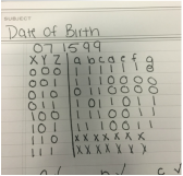
The Truth Table is used to organize the data and to show all the possibilities from a certain variable. variables X Y Z are switches, when the X is 0 the switch is off and when the X is 1 the switch is on. when all three switches are 1 XYZ are all on. abcdefg are the different segments on the seven segment display. when a has a 0 the segment a is not lit.
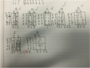
K mappingk mapping simplifies the expressions without using Boolean algebra. k mapping is much simpler than Boolean algebra and faster. The letters with the line over it are "not" and the letters without are present. you have to group the like ones and the x's are don't care variables, so they can be grouped if needed.
Bill of Materials74LS04 IC
74LS00 IC 74LS02 IC 74LS08 IC 74LS32 IC PLD (breadboard) Wires (around 100) Power Source |
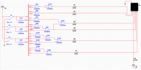
Multisim circuitThe Multisim circuit consisted of 16 gates 6 resistors and three switches
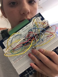
BreadboardingThe bread boarding process was pretty rough. I bread boarded 3 separate times and each time it did not work. Every time I was missing one section of the 7 segment display, but I could not find my mistake so I ended up starting over again. I started bread boarding by placing the IC chips I used 5 IC chips and plenty of wires. I connected the chips to power as well as powering the breadboard. I then followed my simplified expressions for each segment and connected the wires to the proper chips which are embedded in the IC chips. I probably would have gotten my circuit to work if I had asked for help instead of being so stubborn.
|
Conclusion
Considering my circuit did not work I would say I was not very successful in making the birthday project. The hardest part for me was troubleshooting because there were so many wires I could not trace my steps and would have to start all over again. If we had done this project in PLD from the start it would have been much easier for me now because I understand PLD much more than I understand the IC chips. I should have changed which segment I used "nor" for because I had to add 2 more chips making it much more complicated. I should have asked for help earlier on in the project instead of waiting until the last minute when it was too late. I wish I could have gotten the chance to make my circuit work.
